 |
 |
 |
|
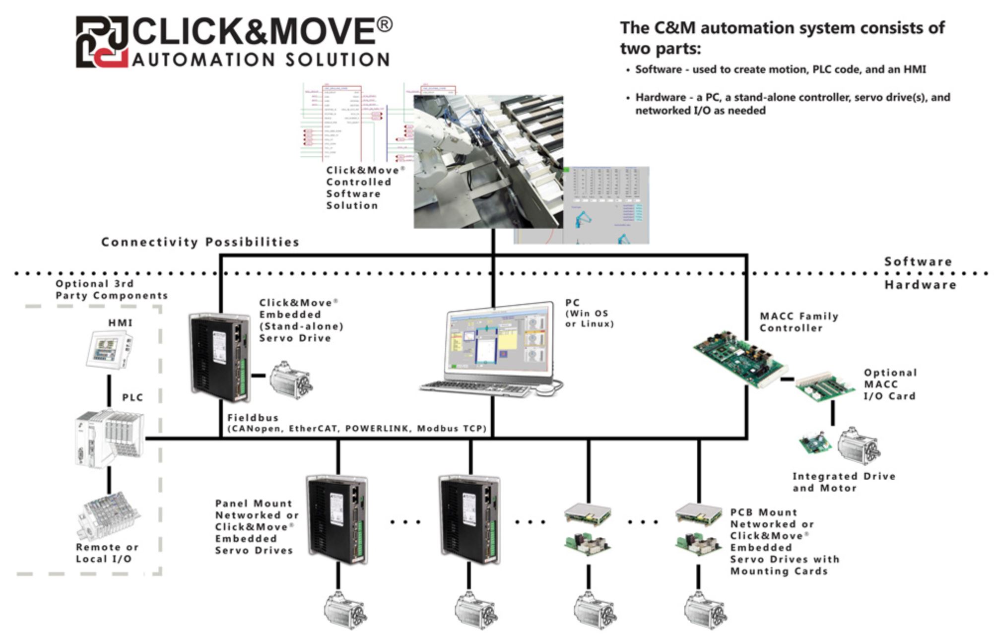
Click&Move® (C&M) is an automation solution designed for OEMs, systems integrators, and end users. It can include motion control, PLC logic, local I/O, and networked I/O. Applications can be simple, single-axis with minimal I/O to complex, multi-axes running in real time. A Click&Move system will consist of both a software component used to create the logic, HMI, and motion profiles and hardware components such as a controller, servo drives, and I/O devices.
 - Combines Motion, PLC, and HMI control
- Based on PLCopen, the global standard for industrial control programming
- Supports CANopen, EtherCAT, and POWERLINK network protocols
- Fully IEC 61131-3 compliant using graphical Function Block Diagrams (FBDs) (pre-configured or user-defined)
- Multiple platforms supported: PC (Win OS and Linux), stand-alone controller (MACC), and ADVANCED Motion Controls drives
Integrated Design EnvironmentThe C&M Integrated Development Environment (IDE) provides the user with a programming environment for a range of applications: - Motion control
- PLC machine control
- G-code file handling for CNC apps
- Process control
- Robotics
The IDE consists of applications to graphically create/edit Function Block Diagram (FBD) based logic schematics and HMI screens, debug application code, organize and archive application code, merge and compare code as well as automating the build/compile status. Where do we start?HMI Requirements: The HMI represents the User Interface Controls. This is what the user will use to interact with the system once it's live. FBD Requirements: The FBD (Function Block Diagram) represents the motion and logic behavior. Depending on their project or their work style, users may want to start with either end. It's ultimately up to them! HMIClick&Move® collects several aspects of motion control, real-time computation, and human interface into a single application. HMIs built in Click&Move are completely customizable. An HMI screen can be as simple as a start/stop button with a drive status read-out. Alternatively, it can be a full operational control screen where users can input commands, enable and disable individual servo drives, display system information, adjust parameters, and even display a dynamic graphical representation of the motion system that updates in real time. As long as the values can be pulled from the function block diagram, the HMI can display any data the user chooses. The editor comes with built in templates for buttons, fields and other elements, so its easy for users to get started. Users can even embed images and change colors and sizes of elements to make their HMI look exactly how they want. - The Function Block Diagram (Eagle) handles the motion, PLC functions, and I/O behavior
- A real-time shell handles communication from the compiled motion program to the fieldbus and HMI (EtherCAT Master stack is embedded in the shell)
- Virtual axis or real axes are selected based on an XML file configuration in the project
- The HMI displays live information and alters variables during real-time operation
MC Blocks and G-Code- Efforts toward keeping within the evolving motion control standards allows for a built-in knowledge base
- This layer of abstraction relieves some of the programming design issues
- PLCopen manuals are distributed within C&M
- Coordinated motion feature follows PLCopen standards
- G-Code handling
Debugging- Application programming using PLCopen FBD language (IEC 61131-3)
- The development process can take place entirely within the users PC
- Virtual axes for motion simulation
- Virtual axis projects can be packaged and exchanged with tech support
- Entirely digital development system helps the support process virtual axes are more portable than real ones
- Debugging tools: graphical and text-based
- Integrated HMI
- Extensive built-in Help - Tutorials, Demos, White Papers, etc.
- Extensive example applications
Solution ArchitecturesA Click&Move® system can be put together in thousands of ways, but most architectures follow one of three main structures. The preferred method depends on the application. PC-BasedIn the PC-based solution below, the C&M development software is used to create motion code, PLC logic, and user interface screens (HMI). The code is compiled for the targeted PC platform and then downloaded. Servo drives and I/O are connected to the PC platform via the network. The PC-based architecture is obviously best-suited for applications where having a PC connected to the system during operation is feasible, such as industrial machines, gantries, and other devices that remain largely stationary. It's also the preferred architecture for any system that has more than 8 motion axes. Motion Automation Control CardThe Motion Automation Control Card (MACC) is a general purpose motion/automation controller with embedded Click&Move® capability. In this scenario, the code is compiled for the MACC platform and then downloaded. The servo drives and I/O are connected to the MACC platform via the network. Optionally, a separate HMI screen can be incorporated via the HDMI connector onboard. The MACC solution is great for mobile applications such as AGV's, but also can be a more cost-effective alternative to the PC-based architecture for applications with 8 axes or fewer. The MACCs also are best suited for applications with a combination of both digital and analog servo drives. Servo Drive-EmbeddedADVANCED Motion Controls offers digital drives that are designed to store and run an embedded C&M program. The C&M development software is used to create motion code and PLC logic. The code is compiled for the targeted drive platform and then downloaded. I/O is local to the drive(s). The servo drive takes over the computational work that would otherwise be left to a PC or stand alone controller, saving both space and money. This is a simple, powerful solution for small applications. It is, however, best used primarily for single-axis applications.
|
|
|
 |
|
 |
|